RV32I_R_Type
✅ DataPath.sv
`timescale 1ns / 1ps

module DataPath (
    input  logic        clk,
    input  logic        reset,
    input  logic [31:0] instrCode,
    input  logic        regFileWe,
    input  logic [ 3:0] aluControl,
    output logic [31:0] instrMemAddr
);

    logic [31:0] aluResult;
    logic [31:0] RFData1, RFData2;
    logic [31:0] PCSrcData, PCOutData;

    assign instrMemAddr = PCOutData;

    RegisterFile U_RegFile (
        .clk       (clk),
        .we        (regFileWe),
        .RA1       (instrCode[19:15]),
        .RA2       (instrCode[24:20]),
        .WA        (instrCode[11: 7]),
        .WD        (aluResult),
        .RD1       (RFData1),
        .RD2       (RFData2)
    );

    alu U_ALU (
        .aluControl(aluControl),
        .a         (RFData1),
        .b         (RFData2),
        .result    (aluResult)
    );

    register U_PC (
        .clk       (clk),
        .reset     (reset),
        .en        (1'b1),
        .d         (PCSrcData),
        .q         (PCOutData)
    );

    adder U_PC_Adder(
        .a         (32'd4),
        .b         (PCOutData),
        .y         (PCSrcData)
    );

endmodule

module alu (
    input  logic  [ 3:0] aluControl,
    input  logic  [31:0] a,
    input  logic  [31:0] b,
    output logic  [31:0] result
    );

    always_comb begin
        result = 32'bx;
        case (aluControl)
            4'b0000: result = a + b;            // add
            4'b0001: result = a - b;            // sub
            4'b0010: result = a & b;            // and
            4'b0011: result = a | b;            // or
            4'b0100: result = a << b;           // sll
            4'b0101: result = a >> b;           // srl
            4'b0110: result = $signed(a) >>> b; // sra
            4'b0111: result = ($signed(a) < $signed(b)) ? 1 : 0;  // slt
            4'b1000: result = (a < b) ? 1 : 0;  // sltu
            4'b1001: result = a ^ b;            // xor
        endcase
    end

    endmodule

module RegisterFile (
    input  logic        clk,
    input  logic        we,
    input  logic [ 4:0] RA1,
    input  logic [ 4:0] RA2,
    input  logic [ 4:0] WA,
    input  logic [31:0] WD,
    output logic [31:0] RD1,
    output logic [31:0] RD2
    );

    logic [31:0] mem [0:2**5-1];

    always_ff @(posedge clk) begin
        if(we) begin
            mem[WA] <= WD;
        end
    end

    assign RD1 = (RA1 != 0) ? mem[RA1] : 32'b0;
    assign RD2 = (RA2 != 0) ? mem[RA2] : 32'b0;

    endmodule

module register (
    input  logic        clk,
    input  logic        reset,
    input  logic        en,
    input  logic [31:0] d,
    output logic [31:0] q
    );

    always_ff @(posedge clk or posedge reset) begin
        if(reset) begin
            q <= 0;
        end
        else begin
            if(en) begin
                q <= d;
            end
        end
    end
    endmodule

module adder (
    input  logic [31:0] a,
    input  logic [31:0] b,
    output logic [31:0] y
    );

    assign y = a + b;

    endmodule
Test를 위한 regFile 수정
module RegisterFile (
    input  logic        clk,
    input  logic        we,
    input  logic [ 4:0] RA1,
    input  logic [ 4:0] RA2,
    input  logic [ 4:0] WA,
    input  logic [31:0] WD,
    output logic [31:0] RD1,
    output logic [31:0] RD2
    );

    logic [31:0] mem [0:2**5-1];

    initial begin   // for Simulation Test
        for (int i = 0; i < 32; i++) begin
            mem[i] = 10 + i;
        end
    end

    always_ff @(posedge clk) begin
        if(we) begin
            mem[WA] <= WD;
        end
    end

    assign RD1 = (RA1 != 0) ? mem[RA1] : 32'b0;
    assign RD2 = (RA2 != 0) ? mem[RA2] : 32'b0;

    endmodule
✅ ControlUnit.sv
Single-Cycle은 combinational logic으로 구현.
wire로 선언한 이유?
=> logic으로는 {instrCode[30], instrCode[14:12]}이게 안됌.
=> 사용하려면 assign으로 연결
logic [6:0] opcode;
logic [3:0] operator;
assign opcode = instrCode[6:0];
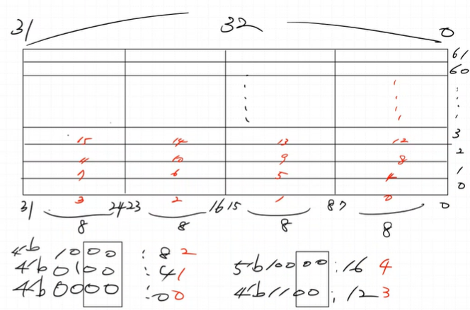
assign operator = {instrCode[30], instrCode[14:12]};
`timescale 1ns / 1ps

module ControlUnit (
    input  logic [31:0] instrCode,
    output logic        regFileWe,
    output logic [ 3:0] aluControl
    );

    wire [6:0] opcode = instrCode[6:0];
    wire [3:0] operator = {instrCode[30], instrCode[14:12]}; // function

    always_comb begin
        regFileWe = 1'b0;
        case (opcode)
            7'b0110011: regFileWe = 1'b1;   // R-Type
        endcase
    end

    always_comb begin
        aluControl = 2'bx;
        case (opcode)
            7'b0110011: begin   // R-Type
                aluControl = 2'bx;
                case (operator)
                    4'b0000: aluControl = 4'b0000;    // ADD
                    4'b1000: aluControl = 4'b0001;    // SUB
                    4'b0111: aluControl = 4'b0010;    // AND
                    4'b0110: aluControl = 4'b0011;    // OR
                    4'b0001: aluControl = 4'b0100;    // SLL
                    4'b0101: aluControl = 4'b0101;    // SRL
                    4'b1101: aluControl = 4'b0110;    // SRA
                    4'b0010: aluControl = 4'b0111;    // SLT
                    4'b0011: aluControl = 4'b1000;    // SLTU
                    4'b0100: aluControl = 4'b1001;    // XOR
                endcase
            end
        endcase
    end

endmodule
✅ ROM.sv
4의 배수로 나눈 값이랑 같다.
`timescale 1ns / 1ps

module ROM (
    input  logic [31:0] addr,
    output logic [31:0] data
    );

    logic [31:0] rom[0:61];

    assign data = rom[addr[31:2]];

endmodule
어셈블리어에 대한 머신 코드이다.
`timescale 1ns / 1ps

module ROM (
    input  logic [31:0] addr,
    output logic [31:0] data
    );

    logic [31:0] rom[0:61];

    initial begin   // for Simulation Test
        // rom[x] = 32'b funct7 _ rs2 _ rs1 _ funct3 _ rd _ op
        // 어셈블리어에 대한 머신 코드이다.
        rom[0] = 32'b0000000_00001_00010_000_01000_0110011; // add  x8, x2, x1
        rom[1] = 32'b0100000_00010_00001_000_01001_0110011; // sub  x9, x1, x2
        rom[2] = 32'b0000000_00100_00011_111_01010_0110011; // and  x10, x3, x4
        rom[3] = 32'b0000000_00011_00100_110_01011_0110011; // or   x11, x4, x3
        rom[4] = 32'b0000000_00101_00001_001_01100_0110011; // sll  x12, x1, x5
        rom[5] = 32'b0000000_00101_00100_101_01101_0110011; // srl  x13, x4, x5
        rom[6] = 32'b0100000_00101_00100_101_01110_0110011; // sra  x14, x4, x5
        rom[7] = 32'b0000000_00010_00100_010_01111_0110011; // slt  x15, x4, x2
        rom[8] = 32'b0000000_00000_00011_011_10000_0110011; // sltu x16, x3, x0
        rom[9] = 32'b0000000_00100_00011_100_10001_0110011; // xor  x17, x3, x4
    end

    assign data = rom[addr[31:2]];

endmodule
✅ MCU.sv
`timescale 1ns / 1ps

module MCU(
    input logic clk,
    input logic reset
    );

    logic [31:0] instrMemAddr, instrCode;

    CPU_RV32I U_CPU_RV32I (
        .clk            (clk),
        .reset          (reset),
        .instrCode      (instrCode),
        .instrMemAddr   (instrMemAddr)
    );

    ROM U_ROM(
        .addr   (instrMemAddr),
        .data   (instrCode)
    );

endmodule
✅ TestBench
`timescale 1ns / 1ps

module tb_RV32I();

    logic clk;
    logic reset;

    MCU U_DUT (.*);

    always#5 clk = ~clk;

    initial begin
        clk = 0;
        reset = 1;
        #20;
        reset = 0;
        #60;
        $finish();
    end

endmodule
✅ 자동 검증 TestBench
`timescale 1ns / 1ps
`include "../../sources_1/new/opcode.vh"
`include "../../sources_1/new/mem_path.vh"
module tb_RV32I();
logic clk;
logic reset;
MCU U_MCU (
.clk (clk),
.reset(reset)
);
always#5 clk = ~clk;
task init;
int i;
for (int i = 0; i < 62; i++) begin
`INSTR_PATH.rom[i] = 32'h00000000;
end
for (int i = 0; i < 32; i++) begin
`RF_PATH.mem[i] = 32'h00000000;
end
endtask
task reset_cpu;
repeat(3) begin
@(posedge clk);
reset = 1;
end
@(posedge clk);
reset = 0;
endtask
logic [31:0] cycle;
logic done;
logic [31:0] current_test_id = 0;
logic [255:0] current_test_type;
logic [31:0] current_output;
logic [31:0] current_result;
logic all_tests_passed = 0;
wire [31:0] timeout_cycle = 25;
initial begin
while (all_tests_passed === 0) begin
@(posedge clk);
if (cycle === timeout_cycle) begin
$display("[Failed] Timeout at [%d] test %s, expected_result = %h, got = %h", current_test_id, current_test_type, current_result, current_output);
$finish();
end
end
end
always_ff @(posedge clk) begin
if (done === 0) cycle <= cycle + 1;
else cycle <= 0;
end
task check_result (input logic [4:0] addr, input [31:0] expect_value, input [255:0] test_type);
done = 0;
current_test_id = current_test_id + 1;
current_test_type = test_type;
current_result = expect_value;
while (`RF_PATH.mem[addr] !== expect_value) begin
current_output = `RF_PATH.mem[addr];
@(posedge clk);
end
cycle = 0;
done = 1;
$display("[%d] Test %s passed!", current_test_id, test_type);
endtask
logic [ 4:0] RS0, RS1, RS2, RS3, RS4, RS5;
logic [31:0] RD0, RD1, RD2, RD3, RD4, RD5;
initial begin
clk = 0;
reset = 1;
#10;
reset = 0;
#10;
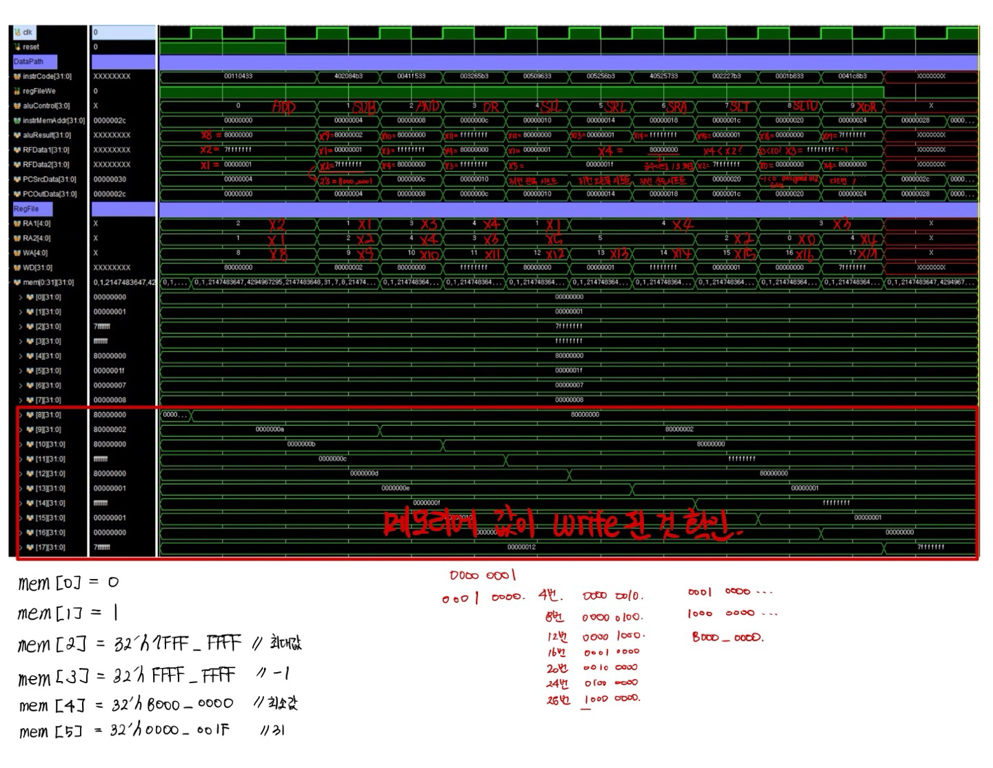
// R-Type TEST
if(1) begin
init();
RS0 = 0; RD0 = 32'h0000_0000;
RS1 = 1; RD1 = 32'h0000_0001;
RS2 = 2; RD2 = 32'h7FFF_FFFF;
RS3 = 3; RD3 = 32'hFFFF_FFFF;
RS4 = 4; RD4 = 32'h8000_0000;
RS5 = 5; RD5 = 32'h0000_001F;
`RF_PATH.mem[RS1] = RD1; //x1 data
`RF_PATH.mem[RS2] = RD2; //x2 data
`RF_PATH.mem[RS3] = RD3; //x3 data
`RF_PATH.mem[RS4] = RD4; //x4 data
`RF_PATH.mem[RS5] = RD5; //x5 data
// Format: {funct7, rs2, rs1, funct3, rd, opcode}
`INSTR_PATH.rom[0] = {`FNC7_0, RS1, RS2, `FNC_ADD_SUB, 5'd8, `OPC_ARI_RTYPE}; // add x8, x2, x1
`INSTR_PATH.rom[1] = {`FNC7_1, RS2, RS1, `FNC_ADD_SUB, 5'd9, `OPC_ARI_RTYPE}; // sub x9, x1, x2
`INSTR_PATH.rom[2] = {`FNC7_0, RS4, RS3, `FNC_AND, 5'd10, `OPC_ARI_RTYPE}; // and x10, x3, x4
`INSTR_PATH.rom[3] = {`FNC7_0, RS3, RS4, `FNC_OR, 5'd11, `OPC_ARI_RTYPE}; // or x11, x4, x3
`INSTR_PATH.rom[4] = {`FNC7_0, RS5, RS1, `FNC_SLL, 5'd12, `OPC_ARI_RTYPE}; // sll x12, x1, x5
`INSTR_PATH.rom[5] = {`FNC7_0, RS5, RS4, `FNC_SRL_SRA, 5'd13, `OPC_ARI_RTYPE}; // srl x13, x4, x5
`INSTR_PATH.rom[6] = {`FNC7_1, RS5, RS4, `FNC_SRL_SRA, 5'd14, `OPC_ARI_RTYPE}; // sra x14, x4, x5
`INSTR_PATH.rom[7] = {`FNC7_0, RS2, RS4, `FNC_SLT, 5'd15, `OPC_ARI_RTYPE}; // slt x15, x4, x2
`INSTR_PATH.rom[8] = {`FNC7_0, RS0, RS3, `FNC_SLTU, 5'd16, `OPC_ARI_RTYPE}; // sltu x16, x3, x0
`INSTR_PATH.rom[9] = {`FNC7_0, RS4, RS3, `FNC_XOR, 5'd17, `OPC_ARI_RTYPE}; // xor x17, x3, x4
reset_cpu();
#10; check_result(8, 32'h8000_0000, "R-Type ADD");
#10; check_result(9, 32'h8000_0002, "R-Type SUB");
#10; check_result(10, 32'h8000_0000, "R-Type AND");
#10; check_result(11, 32'hFFFF_FFFF, "R-Type OR");
#10; check_result(12, 32'h8000_0000, "R-Type SLL");
#10; check_result(13, 32'h0000_0001, "R-Type SRL");
#10; check_result(14, 32'hFFFF_FFFF, "R-Type SRA");
#10; check_result(15, 32'h0000_0001, "R-Type SLT");
#10; check_result(16, 32'h0000_0000, "R-Type SLTU");
#10; check_result(17, 32'h7FFF_FFFF, "R-Type XOR");
end
// I-Type TEST
if(0) begin
init();
reset_cpu();
end
all_tests_passed = 1'b1;
repeat(10) @(posedge clk);
$display("All tests passed!");
$finish();
end
endmodule
경로 매크로 설정
// 레지스터 파일(Register File)
`define RF_PATH   U_MCU.U_CPU_RV32I.U_DataPath.U_RegFile

// 명령어 메모리(Instruction Memory)
`define INSTR_PATH U_MCU.U_ROM
명령어 및 함수 코드 매크로
// List of RISC-V opcodes and funct codes.
// Use `include "opcode.vh" to use these in the decoder

`ifndef OPCODE
`define OPCODE

// Arithmetic instructions
`define OPC_ARI_RTYPE   7'b0110011

// ***** 5-bit Opcodes *****
`define OPC_ARI_RTYPE_5 5'b01100

// Arithmetic R-type and I-type functions codes
`define FNC_ADD_SUB     3'b000
`define FNC_SLL         3'b001
`define FNC_SLT         3'b010
`define FNC_SLTU        3'b011
`define FNC_XOR         3'b100
`define FNC_OR          3'b110
`define FNC_AND         3'b111
`define FNC_SRL_SRA     3'b101

`define FNC7_0  7'b0000000 // ADD, SRL
`define FNC7_1  7'b0100000 // SUB, SRA
`endif //OPCODE
테스트 초기화 / 리셋
레지스터 파일(RF)과 명령어 메모리(ROM)를 모두 0으로 초기화
CPU reset
task init;
    int i;
    for (int i = 0; i < 62; i++) begin
        `INSTR_PATH.rom[i] = 32'h00000000;
    end
    for (int i = 0; i < 32; i++) begin
        `RF_PATH.mem[i] = 32'h00000000;
    end
endtask

task reset_cpu;
    repeat(3) begin
        @(posedge clk);
        reset = 1;
    end
    @(posedge clk);
    reset = 0;
endtask
테스트 결과 검증 및 타임아웃 관리
각 테스트 결과를 자동 검증, 일정 Cycle내에 결과가 나오지 않으면 에러 메시지 출력 후 종료
실패 시 어떤 테스트에서 어떤 값이 잘못되었는지 상세 정보 출력
wire [31:0] timeout_cycle = 25;

initial begin
    while (all_tests_passed === 0) begin
    @(posedge clk);
        if (cycle === timeout_cycle) begin
            $display("[Failed] Timeout at [%d] test %s, expected_result = %h, got = %h", current_test_id, current_test_type, current_result, current_output);
            $finish();
        end
    end
end

always_ff @(posedge clk) begin
    if (done === 0) cycle <= cycle + 1;
    else cycle <= 0;
end

task check_result (input logic [4:0] addr, input [31:0] expect_value, input [255:0] test_type);
    done = 0;
    current_test_id   = current_test_id + 1;
    current_test_type = test_type;
    current_result    = expect_value;
    while (`RF_PATH.mem[addr] !== expect_value) begin
        current_output = `RF_PATH.mem[addr];
        @(posedge clk);
    end
    cycle = 0;
    done = 1;
    $display("[%d] Test %s passed!", current_test_id, test_type);
endtask
R-Type 명령어 테스트
// R-Type TEST
    if(1) begin
        init();

        RS0 = 0; RD0 = 32'h0000_0000;
        RS1 = 1; RD1 = 32'h0000_0001;
        RS2 = 2; RD2 = 32'h7FFF_FFFF;
        RS3 = 3; RD3 = 32'hFFFF_FFFF;
        RS4 = 4; RD4 = 32'h8000_0000;
        RS5 = 5; RD5 = 32'h0000_001F;

        `RF_PATH.mem[RS1] = RD1; //x1 data
        `RF_PATH.mem[RS2] = RD2; //x2 data
        `RF_PATH.mem[RS3] = RD3; //x3 data
        `RF_PATH.mem[RS4] = RD4; //x4 data
        `RF_PATH.mem[RS5] = RD5; //x5 data

        // Format: {funct7, rs2, rs1, funct3, rd, opcode}
        `INSTR_PATH.rom[0] = {`FNC7_0, RS1, RS2, `FNC_ADD_SUB, 5'd8, `OPC_ARI_RTYPE};  // add  x8, x2, x1
        `INSTR_PATH.rom[1] = {`FNC7_1, RS2, RS1, `FNC_ADD_SUB, 5'd9, `OPC_ARI_RTYPE};  // sub  x9, x1, x2
        `INSTR_PATH.rom[2] = {`FNC7_0, RS4, RS3, `FNC_AND,     5'd10, `OPC_ARI_RTYPE}; // and  x10, x3, x4
        `INSTR_PATH.rom[3] = {`FNC7_0, RS3, RS4, `FNC_OR,      5'd11, `OPC_ARI_RTYPE}; // or   x11, x4, x3
        `INSTR_PATH.rom[4] = {`FNC7_0, RS5, RS1, `FNC_SLL,     5'd12, `OPC_ARI_RTYPE}; // sll  x12, x1, x5
        `INSTR_PATH.rom[5] = {`FNC7_0, RS5, RS4, `FNC_SRL_SRA, 5'd13, `OPC_ARI_RTYPE}; // srl  x13, x4, x5
        `INSTR_PATH.rom[6] = {`FNC7_1, RS5, RS4, `FNC_SRL_SRA, 5'd14, `OPC_ARI_RTYPE}; // sra  x14, x4, x5
        `INSTR_PATH.rom[7] = {`FNC7_0, RS2, RS4, `FNC_SLT,     5'd15, `OPC_ARI_RTYPE}; // slt  x15, x4, x2
        `INSTR_PATH.rom[8] = {`FNC7_0, RS0, RS3, `FNC_SLTU,    5'd16, `OPC_ARI_RTYPE}; // sltu x16, x3, x0
        `INSTR_PATH.rom[9] = {`FNC7_0, RS4, RS3, `FNC_XOR,     5'd17, `OPC_ARI_RTYPE}; // xor  x17, x3, x4

        reset_cpu();

        #10; check_result(8,  32'h8000_0000, "R-Type ADD");
        #10; check_result(9,  32'h8000_0002, "R-Type SUB");
        #10; check_result(10, 32'h8000_0000, "R-Type AND");
        #10; check_result(11, 32'hFFFF_FFFF, "R-Type OR");
        #10; check_result(12, 32'h8000_0000, "R-Type SLL");
        #10; check_result(13, 32'h0000_0001, "R-Type SRL");
        #10; check_result(14, 32'hFFFF_FFFF, "R-Type SRA");
        #10; check_result(15, 32'h0000_0001, "R-Type SLT");
        #10; check_result(16, 32'h0000_0000, "R-Type SLTU");
        #10; check_result(17, 32'h7FFF_FFFF, "R-Type XOR");
    end
✅ 결과
[Failed]
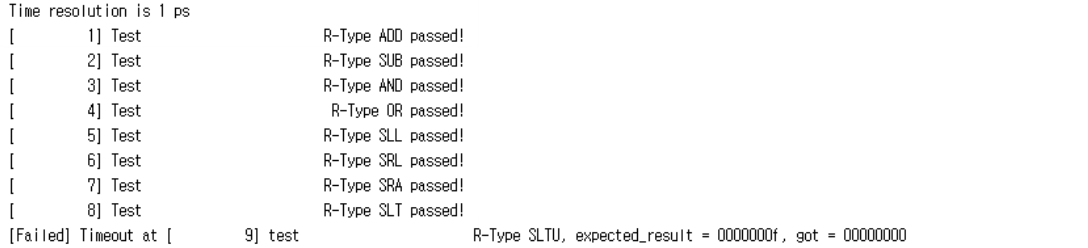
[Passed]
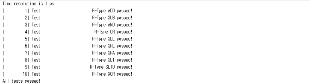
[Simulation_Result]